
What Causes Carbide Insert Chipping During CNC Turning?
Carbide insert chipping is a frustrating problem in CNC turning because it often appears without much warning. The tool may produce good parts for a while, then a small section of the cutting edge breaks away. Surface finish changes, dimensions start to drift, and the next insert may fail in exactly the same way.
When this happens, replacing the insert is usually the easiest response. It is not always the right one.
A chipped insert is often telling you something about the cutting process. The problem may come from excessive cutting force, interrupted machining, vibration, an unsuitable insert geometry, or simply a grade that does not match the workpiece. In many cases, the damage pattern on the insert provides more information than the failure itself.
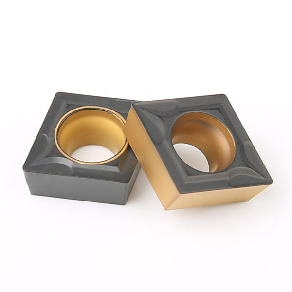
Start With the Chipping Pattern
Before changing anything, look closely at where the carbide has failed.
If only the very edge is chipped, the cutting edge may be taking more mechanical impact than it can tolerate. A broken corner points to a different set of possibilities, particularly when the tool is entering an interrupted cut. If the damage appears gradually after several parts, heat and wear deserve more attention.
This distinction matters because not every chipped insert needs a tougher grade. Sometimes the insert is fine and the real issue is tool overhang, unstable workholding, or an overly aggressive feed.
In production, it is useful to record when the chipping starts. Does the first part already show damage? Does it happen only on a certain diameter? Does it appear when the tool reaches a hole or keyway? Does the insert last for 20 parts and then begin to deteriorate?
Those details can quickly narrow the problem down.
Cutting Load May Be Too High
Feed rate and depth of cut are usually among the first things worth checking.
A higher feed increases the load applied to the cutting edge. A larger depth of cut increases the amount of material being removed and can push cutting forces even higher. Neither setting is automatically wrong, but the combination may be too demanding for the insert and the machine setup.
This is particularly noticeable during rough turning. An insert that works perfectly during light finishing may chip when it is used for a heavy roughing pass.
Cutting speed also needs to be considered, but it should not be treated as the only variable. Raising speed changes the thermal conditions at the cutting edge. In some materials, running too fast accelerates wear. At an unsuitable speed, other problems such as built-up edge may appear.
A practical way to troubleshoot the process is to establish a stable cutting condition first, then make one change at a time. Large parameter changes across speed, feed, and depth of cut make it difficult to identify what actually solved the problem.

A Stronger Insert Geometry May Be Needed
The sharpest cutting edge is not always the best cutting edge.
For light machining and finishing work, a sharp positive geometry can reduce cutting forces and leave a good surface finish. The trade-off is that a thin, sharp edge generally has less support when it meets an unstable or interrupted cut.
Heavy roughing is different. When the insert has to deal with higher loads, a stronger geometry or edge preparation may provide better stability.
This becomes especially important when the workpiece contains holes, slots, keyways, cast surfaces, or other irregular features. The cutting edge is repeatedly loaded and unloaded instead of staying in a continuous cut. Small impacts that seem insignificant during one pass can eventually create a microfracture in the carbide.
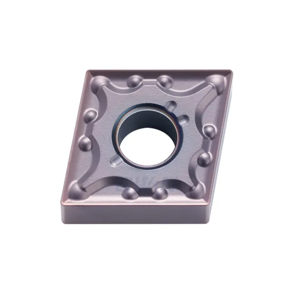
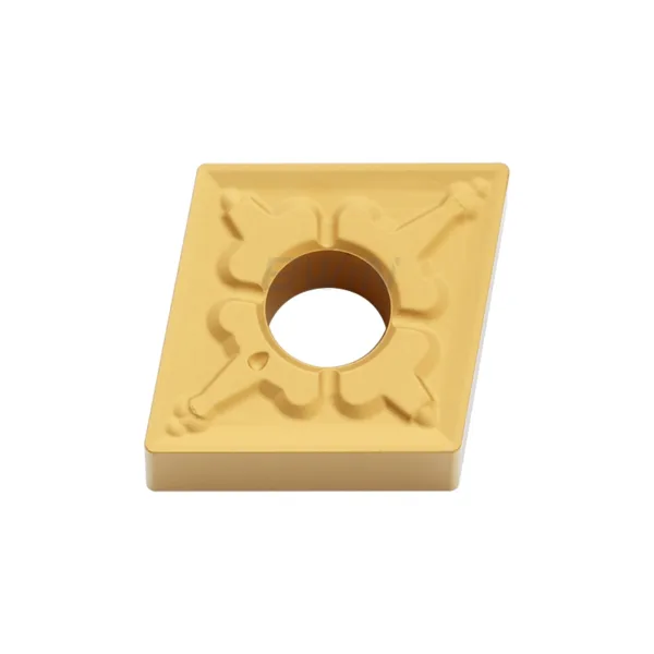
BWIN’s turning insert range includes common geometries such as CCMT, CNMG, DCMT, and DNMG. These shapes are designed for different cutting conditions, so selecting an insert should start with the machining operation rather than the part number alone.
The Carbide Grade May Not Match the Job
Insert grade is another area where problems are often misdiagnosed.
Different carbide grades balance hardness, wear resistance, and toughness in different ways. A grade that performs well during stable continuous turning may not tolerate repeated impacts as well as a tougher grade.
The workpiece material matters just as much. Stainless steel, cast iron, carbon steel, hardened steel, and non-ferrous metals do not place the same demands on the cutting edge.
This is why choosing a grade based only on the material name is not enough. The actual process also matters. Are you roughing or finishing? Is the cut continuous? Is the machine rigid? Is the component thin-walled? Is the tool extended far from the holder?
A good insert grade needs to suit the entire cutting environment, not just the workpiece.
Vibration Can Destroy a Good Insert
Sometimes the insert gets blamed for a problem that starts elsewhere.
Tool overhang is a good example. When the tool extends too far from the holder, rigidity drops. Small amounts of vibration can then become significant at the cutting edge. The insert may still look correct, but the repeated impact can eventually cause chipping.
The same applies to workholding. A poorly supported or thin-walled component can move under cutting force. Once the workpiece starts to deflect, the cutting load becomes unstable. The edge may alternate between heavy contact and light contact, which is hard on carbide.
If the same insert chips repeatedly on the same machine, check the whole setup before changing insert grades. Tool overhang, holder condition, insert seating, clamping force, workpiece support, and chucking should all be considered.
A rigid setup often solves problems that parameter changes cannot.
Interrupted Cutting Is Harder on the Cutting Edge
Interrupted cutting deserves special attention because it changes the nature of the load.
In a normal continuous turning operation, the cutting edge remains engaged with the material for a relatively steady period. With an interrupted cut, the edge enters the workpiece, leaves it, and then hits the material again.
That repeated impact can be especially hard on carbide.
The issue commonly appears when machining parts with cross holes, keyways, slots, cast skins, forged surfaces, or irregular profiles. In these applications, an insert selected for maximum wear resistance may not be the best choice if it does not have enough toughness.
The first sign may be a tiny chip on the corner. After several passes, the damage can become much larger.
When interrupted cutting is unavoidable, it is usually better to prioritize edge stability and machine rigidity before trying to push productivity higher.
Built-Up Edge Can Cause Secondary Chipping
Material sticking to the cutting edge is another situation worth checking, particularly when machining materials that tend to form built-up edge.
Once material adheres to the insert, the effective cutting geometry changes. The tool no longer cuts with the profile it was designed to have. When that built-up material eventually breaks away, it can pull material from the carbide edge with it.
This type of damage can be confusing because the operator may only notice the chipped insert after the built-up edge has disappeared.
Look for signs of material adhesion or an irregular cutting edge. If they appear together, changing the insert alone may not solve the problem. Cutting speed, insert geometry, lubrication, and the choice of grade may all need to be reconsidered.
Nose Radius Also Affects Edge Stability
Nose radius has a direct relationship with cutting force and edge strength.
A larger nose radius can provide a stronger cutting edge and support better surface finish under the right conditions. At the same time, it can increase radial forces. On a rigid machine this may not be an issue, but on a slender component or less rigid setup, the additional force can contribute to vibration.
A smaller nose radius reduces some cutting forces and can be useful in certain finishing operations. However, the smaller edge area provides less support when the insert encounters impact or excessive feed.
This is why simply choosing the largest available nose radius is not a reliable solution. The correct radius depends on the part geometry, feed rate, depth of cut, surface-finish requirement, and rigidity of the setup.
Heat and Wear Can Lead to Chipping
Not every chipped edge starts with a sudden impact.
In longer production runs, wear can gradually weaken the cutting edge. As the edge becomes worn, cutting forces and temperature can change. Eventually, a small worn section may fracture and turn into visible chipping.
This is one reason why insert life should not be judged only by whether the cutting edge is still producing acceptable parts. An insert that is technically still cutting may already be approaching the point where edge failure becomes more likely.
If inserts chip only after a predictable number of parts, look at tool life, cutting speed, cooling conditions, and wear progression rather than treating the failure as a one-off event.
A Simple Troubleshooting Sequence
When carbide inserts begin to chip, it helps to avoid changing several things at once.
Start with the machining setup. Check whether the insert is seated correctly, whether the toolholder is secure, and whether the workpiece is properly supported. Look at tool overhang as well.
Next, identify whether the cut is continuous or interrupted. If the chipping occurs at a hole, slot, shoulder, or irregular surface, mechanical impact becomes a strong suspect.
Then review the cutting parameters. Check whether feed or depth of cut has recently increased and whether the current combination is appropriate for the insert.
After that, look at insert geometry and grade. A sharper geometry may be unnecessarily fragile for roughing or interrupted cutting, while a grade focused heavily on wear resistance may not provide enough toughness for an unstable process.
This sequence is usually more productive than simply switching from one insert brand or model to another.
Matching the Insert to the Actual Turning Condition
There is no single carbide turning insert that performs equally well across every CNC application.
A finishing operation on a rigid machine has very different requirements from heavy roughing on a large steel component. Stainless steel turning is different from cast iron. Continuous turning is different from interrupted cutting. A short, rigid tool setup is different from a long-reach boring or turning arrangement.
The insert should therefore be selected around the complete machining condition.
For BWIN, this means looking beyond the insert designation itself and considering the geometry, grade, nose radius, workpiece material, and cutting application together. The company’s carbide turning insert range covers several commonly used insert forms for CNC turning, giving manufacturers options for different machining requirements.
Final Thoughts:
Carbide insert chipping is usually not a random failure. In most cases, the cutting edge is reacting to something in the process.
Sometimes the feed is too aggressive. Sometimes the insert geometry is too delicate for the operation. Sometimes the grade does not have enough toughness. In other cases, the real cause is vibration, poor workholding, excessive tool overhang, or interrupted cutting.
The most useful approach is to treat the chipped edge as evidence. Look at where it failed, when it failed, and what the tool was doing at that moment. Once those clues are combined with the cutting conditions, it becomes much easier to decide whether the process needs a parameter change, a different insert geometry, or a different carbide grade.
That is usually more effective than simply installing another insert and hoping it lasts longer.
Add comment